


Importance of Materials Selection for Printed Circuit Boards
Importance of Materials Selection for Printed Circuit Boards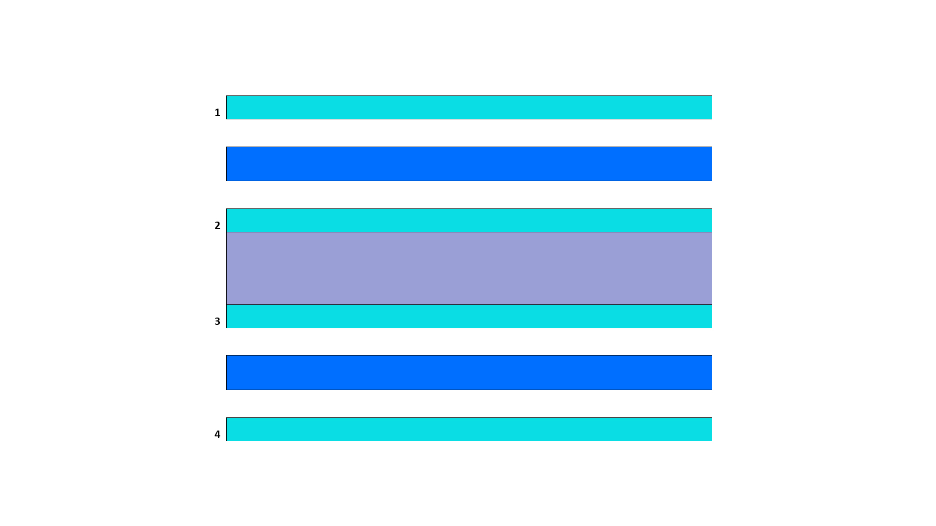
For designers, it is important to make the right choices for printed circuit board materials, as their selection affects not only the overall performance of the board, but also the circuit board price. The electrical and thermal properties of the materials affect the design even before the board can get to the manufacturing stage. This is important not only for achieving the best results, but also for saving time and money in the long run.
For selecting printed circuit board materials, designers must consider them at the PCB stack-up level, and choose materials for different layers consisting of:
- PCB Laminates
- Prepreg
- Copper Foil
PCB Materials for Stack-Up
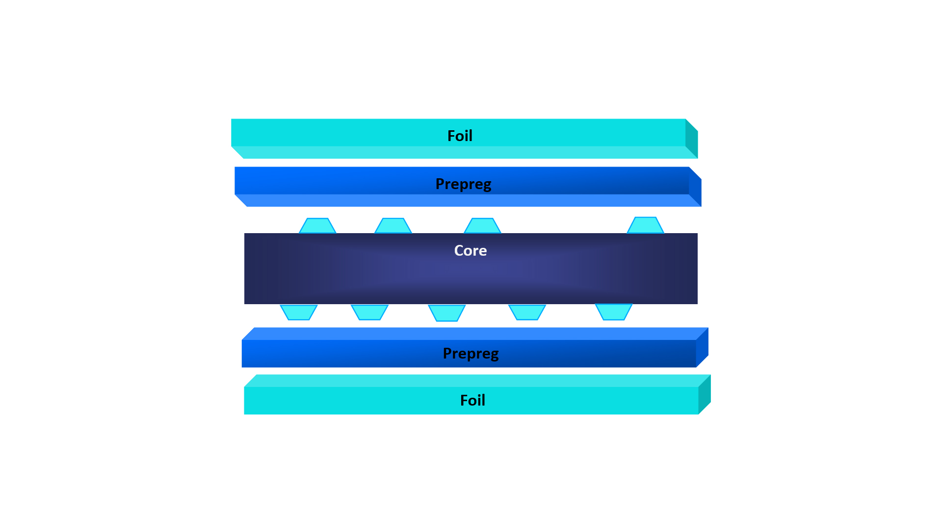
The stack-up is the construction of a multi-layered electronic circuit board in sequential order. Typically, a stack-up consists of cores, prepreg, and foil. Most designers keep stack-up construction symmetrical around the central core.
PCB Core
The core of the PCB is made of laminates and copper foils, with prepreg bonding the copper foil with the laminate. Multi-layered PCBs may have several cores with prepreg bonding them sequentially.
Basic Properties of PCB Laminates
PCB laminates are dielectric materials, for which the designer must consider various properties such as Electrical Properties like Dielectric Constant (Dk) and Loss Tangent (Tan d) or Dissipation Factor (Df), and Thermal Properties like Glass Transition Temperature (Tg), Decomposition Temperature (Td), Thermal Conductivity (k), and Coefficient of Thermal Expansion (CTE).
Electrical Properties of PCB Laminates
Dielectric Constant (Dk) :
For impedance considerations and signal integrity, designers must consider the dielectric constant of the electronic circuit board laminate they plan to use. This is a critical factor for high-speed and high-frequency operation of electrical circuits on the printed circuit board. For most PCB materials, the dielectric constant varies from 2.5 to 4.5, with a lower Dk favoring higher frequency and speed of operation.
Loss Tangent (Tan d) or Dissipation Factor (Df) :
The resistive and reactive currents within the dielectric usually have a phase angle between them. The tangent of this phase angle is the loss tangent or dissipation factor of the dielectric. Increasing values of Df denotes higher dielectric loss, with high losses accounting for slower substrates. Higher dielectric loss also means the signal loses its energy as it travels, resulting in a loss of signal integrity.High-frequency materials show very low Df, and the variation of the Df with changes in frequency is also very low. High-frequency PCB material usually have Df values ranging from 0.001 to 0.030.
Thermal Properties
Glass Transition Temperature (Tg) :
This is the temperature range in °C where the PCB laminate material transforms from the usual rigid state to a softened or plastic state. As the material cools, its properties revert to the original rigid state. Designers must know the temperature range the PCB will undergo during reflow soldering and in actual operation, and select a suitable substrate material with a larger glass transition temperature range.
Decomposition Temperature (Td) :
This is the temperature range in °C where the PCB material starts to decompose chemically and loses at least 5% of its original mass. The designer must select a PCB material that has a decomposition temperature higher than what the PCB assembly will undergo during reflow soldering, and during operation.
Thermal Conductivity (k) :
For good thermal management, selecting a material with good thermal conductivity is important. This property of the PCB material is the rate at which it conducts heat. A high figure of k denotes the material is a good conductor of heat. The expression for thermal conductivity of rate of heat transfer of the material is in watts per meter per degree Celsius or W/M °C).
Coefficient of Thermal Expansion (CTE) :
This is a very important parameter as it defines the rate at which the PCB material will expand of contract with changes in temperature. If the CTE of the material differs much from copper, the heating or cooling of the PCB may cause interconnection issues at vias. Designers usually choose materials with CTE value close to that of copper.How to Select PCB Materials
For ease of working, designers divide electronic circuit board materials into four broad categories like Normal Speed and Normal Loss, Medium Speed and Medium Loss, High Speed and Low-Loss, and Very High-Speed and Very Low-Loss.
Normal Speed and Normal Loss Materials :
These are the most common printed circuit board materials, such as the glass epoxy or FR4 family. These materials do not have a very flat response of dielectric constant versus frequency response. That means their dielectric loss increases with frequency. This limits their suitability for digital/analog applications to only a few GHz. Isola 370HR is an example of this type of PCB material.
Medium Speed and Medium Loss Materials :
These materials have a comparatively flatter dielectric constant versus frequency response as compared to the first category. At the same time, their dielectric loss is about half that for normal speed and normal loss materials. This category of PCB materials is suitable for applications operating up to about 10 GHz. Nelco N7000-2 HT is an example of this type of PCB material.
High Speed and Low-Loss Materials :
With still flatter dielectric constant versus frequency response as compared to category 1 and 2, these offer low losses as the operational frequency rises. Apart from low losses, this category of materials also exhibits comparatively lower electrical noise. Isola I-Speed is an example of this type of materials.
Very High-Speed and Very Low-Loss Materials :
These materials exhibit the flattest dielectric loss versus frequency curve, and have extremely low dielectric loss. This category of materials is suitable for applications involving up to about 20 GHz. Tachyon 100G and Isola I-Tera MT40 are examples of this type of PCB materials.Signal Loss in PCB Materials
The material that a designer chooses for their PCB affects the signal integrity in high-frequency and high-speed circuits. Signal loss in PCBs has two components:
- Dielectric Loss
- Copper Loss
Dielectric Loss :
Dielectric loss takes place in the substrate, which heats up as it absorbs the signal. The higher the absorption, higher is the heat, and higher is the signal loss. Moreover, the loss increases with rise in frequency. The designer has to balance the circuit board price with the type of PCB material chosen and the amount of loss the circuit can functionally accept.
Copper Loss :
The current passing through the copper traces of an electronic circuit board causes ohmic losses due to the resistance of the material. Higher frequencies cause eddy currents inside the copper traces, resulting in skin effect that forces the current flow to occupy the outer parts of the cross section of the trace. The net effect of this is to increase the resistance of the trace, and hence the heat losses. For instance, if the trace has a nickel finish, most of the current will pass through the nickel as the frequency of the signal increases.One way to get around the above is to use wider traces, provided the increase in the board area is acceptable. Most designers prefer to use low profile, highly annealed copper foil, such as rolled copper.
Conclusion
Careful selection of materials and proper stack-up design of printed circuit boards goes a long way in improving signal integrity, reducing cross-talk, and reducing electromagnetic emissions significantly. Other benefits of a careful choice of PCB materials are controlled impedance of traces, reduction in the size of the board, improvement in the routing density. Introduction of ground and power planes in electronic circuit board helps further.

